7.3.4 Environment structure
7.3.4.1 General
The environment consists of the terrain, buildings, objects, and traffic areas, for example, roads. It also includes all stationary traffic items, such as traffic signals, signs, or lights.
The environment’s 3D geometry is structured according to the node structure defined in Section 7.3.4.3, "Model structure". The structure begins with a root node, which is the parent of all other nodes. If applicable, the origin of the root node should match that of the corresponding OpenDRIVE map. Children of the root node are terrain, environment objects, and the road network. The latter is further detailed by its child nodes, the drivable area, sidewalks, road marks, road objects, and signals.
An example environment asset is provided in the examples folder.
Groups with a local transform are indicated in the structure by a (T). This indicator is used in the documentation only and shall not be part of the actual node name.
An example of an environment asset can be found in the examples folder of the GitHub repository.
7.3.4.2 Naming convention
Every object has a unique name and represents a part of the environment. All included meshes are part of a group that indicates which object type they represent. All meshes should be given meaningful names.
Users may define additional groups and keywords that are not part of the standard.
7.3.4.3 Model structure
7.3.4.3.2 Grp_Root
The environment consists of the terrain, buildings, objects, and traffic areas, for example, roads. It also includes all stationary traffic items, such as traffic signals, signs, or lights.
If applicable, the origin of the root should match the inertial coordinate frame of a corresponding ASAM OpenDRIVE map.
| Grp_Root | |
|---|---|
Origin |
Origin matching the inertial coordinate frame of an associated ASAM OpenDRIVE map (if available) |
x-axis |
Pointing to the right (east for maps with geographic reference) |
y-axis |
Pointing up (north for maps with geographic reference) |
z-axis |
Pointing out of the drawing plane (up for maps with geographic reference) |
7.3.4.3.3 Grp_Terrain
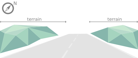
The terrain is characterized by the environment’s ground structure, such as hills, mountains, or flat territory, meaning the landscape in general. It does not include local elevations like vegetation, buildings, or other human-made structures.
Grp_Terrain is used as parent for all nodes defining the terrain of an environment. It shares the coordinate system with Grp_Root, see Table 102.
7.3.4.3.4 Grp_Environment_Objects
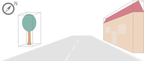
Environment objects include buildings, vegetation, and any other (stationary) objects in the environment. An environment object causes a local elevation or other addition to the terrain.
Grp_Environment_Objects is used as parent for all environment objects in an environment. It shares the coordinate system with Grp_Root, see Table 102.
7.3.4.3.5 Grp_Buildings
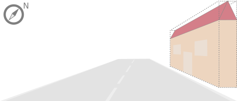
A building is a human-made structure and includes houses, towers, or skyscrapers.
Grp_Buildings is used as parent for all buildings of a Grp_Environment_Objects. It shares the coordinate system with Grp_Root, see Table 102.
7.3.4.3.6 Grp_Vegetation
Vegetation includes all organic growth or plants that are part of the landscape. Vegetation can grow on the terrain or on human-made structures, for example between roads and buildings.
Grp_Vegetation is used as parent for all vegetation objects of a Grp_Environment_Objects. It shares the coordinate system with Grp_Root, see Table 102.

7.3.4.3.7 Grp_Road_Network
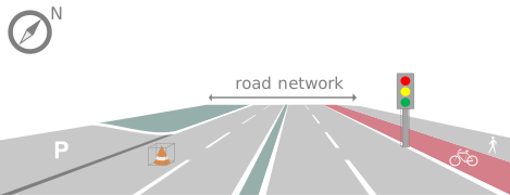
The road network is the entirety of a road. It includes the drivable area, sidewalks, and any other traffic objects, such as traffic signals, signs, or traffic lights.
Grp_Road_Network is used as parent for all nodes defining the road network of an environment. It shares the coordinate system with Grp_Root, see Table 102.
7.3.4.3.8 Grp_Drivable_Area
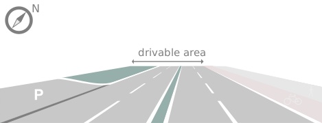
The drivable area is a traffic space that is dedicated to vehicles. It is the surface part of the road structure on which vehicles drive and includes lanes and parking areas. The drivable area for ASAM OpenMATERIAL 3D is comparable to the scope of the ASAM OpenDRIVE standard for on-road use cases.
Grp_Drivable_Area is used as parent for all nodes defining the drivable area of a road network. It shares the coordinate system with Grp_Root, see Table 102.
7.3.4.3.9 Grp_Sidewalks
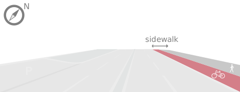
A sidewalk is a traffic space that is dedicated to pedestrians and sometimes cyclists. Sidewalks are usually adjacent to the drivable area.
Grp_Sidewalks is used as parent for all nodes defining the sidewalks of a road network. It shares the coordinate system with Grp_Root, see Table 102.
7.3.4.3.10 Grp_Road_Marks
Road marks include any markings on the road and traffic spaces.
Grp_Road_Marks is used as parent for all nodes defining the road marks of a road network. It shares the coordinate system with Grp_Root, see Table 102.

7.3.4.3.11 Grp_Road_Objects
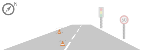
Road objects include all other objects on or nearby the road, excluding signals.
Grp_Road_Objects is used as parent for all road objects of a road network. It shares the coordinate system with Grp_Root, see Table 102.
7.3.4.3.12 Grp_Signals
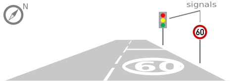
A signal in the context of traffic is a visual sign used to control the flow of traffic. A traffic signal can be both a sign and a light. Signals describe the relevant area or volume of a traffic signal only. Posts and gantries are considered road objects.
Grp_Signals is used as parent for all signals of a road network. It shares the coordinate system with Grp_Root, see Table 102.
7.3.4.3.13 Grp_Sign_<signal_idx> (T)
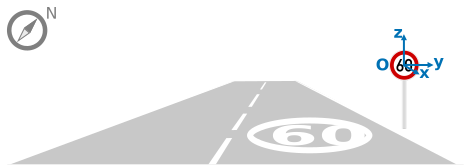
Traffic signs belong to traffic signals. They are indexed using a <signal_idx>. The <signal_idx> can be taken over from ASAM OpenDRIVE or ASAM OSI. If no predefined indices exist, they can be generated by iterating over all signals from (0,…,n). The indices are used for both traffic signs and traffic lights. A traffic sign cannot have the same index as a traffic light in a single environment.
| Grp_Sign | |
|---|---|
Origin |
Geometric center of the sign’s face |
x-axis |
Concentric and coaxial to the surface normal of the sign face |
y-axis |
Completes the right-handed coordinate system |
z-axis |
Perpendicular to the x-axis, pointing vertically upwards |
7.3.4.3.14 Grp_Traffic_Light_<signal_idx> (T)
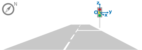
Traffic lights belong to traffic signals. They show temporary changes in illumination. The <signal_idx> can be taken over from ASAM OpenDRIVE or ASAM OSI. If no predefined indices exist, they can be generated by iterating over all signals from (0,…,n). The indices are used for both traffic signs and traffic lights. A traffic light cannot have the same index as a traffic sign in a single environment.
| Grp_Traffic_Light | |
|---|---|
Origin |
Geometric center of the traffic light signal area surface |
x-axis |
Concentric and coaxial to the surface normal of the signal area surface |
y-axis |
Completes the right-handed coordinate system |
z-axis |
Perpendicular to the x-axis, pointing vertically upwards |
If the index of a traffic light (<signal_idx>) is aligned with an ASAM OpenDRIVE map, lighting of individual bulbs can be implemented by corresponding child nodes implementing the ASAM OpenMATERIAL 3D lighting concept.
To enable dynamic light state control by ASAM OpenSCENARIO XML scenarios and ASAM OSI messages, the naming of these child nodes should follow the scheme Grp_Bulb_<bulb_idx>.
Here, <bulb_idx> should be counted from left to right (in positive y-direction) and from bottom to top (in positive z-direction) to align with osi3::TrafficLight.
Bulb-specific semantic color defined by osi3::TrafficLight::Classification shall be implemented by the RGB light color in ASAM OpenMATERIAL 3D:
| Bulb Color | |
|---|---|
COLOR_RED |
255,0,0 |
COLOR_YELLOW |
255,255,0 |
COLOR_GREEN |
0,255,0 |
COLOR_BLUE |
0,0,255 |
COLOR_WHITE |
255,255,255 |
Bulb-specific icons can be implemented by emissive materials and the maskingTextureUri property in ASAM OpenMATERIAL 3D.
Here, the naming of the masking textures should correspond to the naming used in ASAM OSI, for example, "ICON_ARROW_STRAIGHT_AHEAD.png".
Instead of masking textures, emissive textures that are already included in the 3D data file can be used.
For the implementation of ASAM OpenSCENARIO XML semantic traffic light states, child nodes of bulbs can be grouped by parent group nodes per traffic light, for example, Grp_Bulbs_Attention_Stop, Grp_Bulbs_Go, and Grp_Bulbs_Stop: