Introduction
Overview
Motivation
Accurate sensor simulation that replicates physical phenomena is essential for evaluating the safety of AD/ADAS (automated driving/automated driving assistance systems) in virtual environments.
However, previous simulations were limited by computational power and memory, making them visually believable but not physically accurate. Consequently, these simulations were mainly used in the early development stages, where precise physical modeling was not necessary.
With increased computing power and improved simulation techniques, virtual testing now plays a crucial role at all stages of system development. This aligns with the growing need to accurately represent the real world in simulations, known as digital twins, especially as the demand for physical sensor simulation rises. A fundamental step in virtually describing the real world is providing a full physical description of all objects, including their material properties and 3D geometries.
Standardizing the representation of data and attributes, such as scenarios, road data, and asset data, is extremely important for AD/ADAS simulation. This promotes data circulation and ensures consistent results across different systems.
Standardization efforts have been made for scenarios and road data using ASAM OpenSCENARIO, ASAM OpenDRIVE, ASAM OpenCRG, and other standards. ASAM OpenMATERIAL 3D advances standardization by providing standardized definitions of material properties and 3D geometry.
The two main segments of ASAM OpenMATERIAL 3D
ASAM OpenMATERIAL 3D is divided into distinct yet complementary segments enabling a modular approach to implementation. Key to this is the distinction between material and geometry. Based on specific use cases, users of ASAM OpenMATERIAL 3D can implement the standard for one or both segments. At least one of the two segments shall be implemented to conform with the standard.
-
Material, see Section 8, "Material": This segment includes definitions and file formats for storing and exchanging material properties. These properties can be physical, such as surface roughness, permittivity, and index of refraction, or measured data, like wavelength and angle-dependent reflectance values. Tools or systems focusing on material properties can implement support for the material segment. For example: “This tool supports ASAM OpenMATERIAL 3D: Material”.
-
Geometry, see Section 7, "Geometry": This segment contains structures for different object classes. These structures define uniform node structure, naming scheme and coordinate systems to enable exchange, common integration and animation of 3D models. Tools or systems working primarily with geometric data, such as 3D models or spatial structures, can implement support for the geometry segment. For example: “This tool supports ASAM OpenMATERIAL 3D: Geometry”.
For a full exchange of simulation-ready 3D assets however, both segments must be supported. Systems or tools providing full support for both material and geometric data can be described as follows: “This tool supports ASAM OpenMATERIAL 3D”.
A list of use cases examples can be found in Section 6, "Use cases", each highlighting its relevance to the material segment, the geometry segment, or both.
Structure and file formats
ASAM OpenMATERIAL 3D defines various file formats for specifying assets, material properties, and the mapping between them. Figure 1 illustrates these file formats and their interconnections. The definitions of the geometry related data formats marked in red can be found in the geometry segment. The definitions of the material related data formats marked in blue can be found in the material segment.
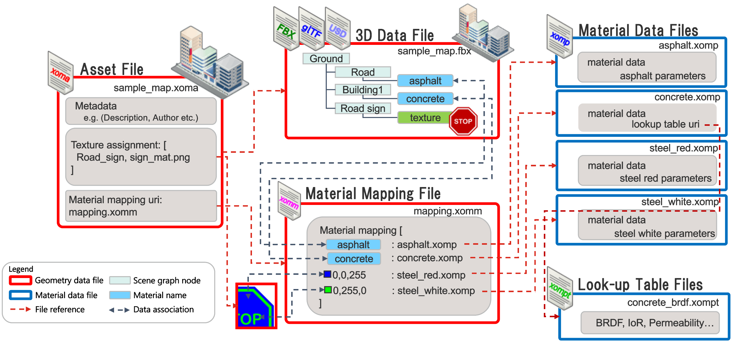
The first interaction with an ASAM OpenMATERIAL 3D-compliant 3D model is through the asset file.
The asset file is a JSON file with the file extension .xoma (ASAM OpenMATERIAL 3D Asset). A detailed definition of the asset file JSON schema is given in Section 7.5, "Asset schema". The asset file shall have the same name as a corresponding 3D data file in glTF, FBX, or USD format. To facilitate instancing and allow implementation of variants of an asset, multiple asset files may be linked to a single 3D model file by adding a string separated by a dot (.) as a suffix to the asset file name. It contains metadata, such as description, unique identifier, version information, copyright details, and so on. It also includes a material texture assignment table, allowing dedicated material mapping textures to be assigned to materials within 3D data files. This enables comprehensive material properties to be mapped to the geometry at a texture level. Each texel of this dedicated texture contains a 32 Bit code (8 Bit values in the RGBA channels) which is mapped to a material property file (.xomp) in a separate material mapping file (.xomm), linked in the asset file with a URI. For the mapping currently only the RGB channels are used (first 24 Bits). The last channel is reserved for future use. An example asset is provided in the examples folder of the repository.
The 3D data file is a standard 3D model file in glTF, FBX, or USD format. Multiple formats can exist in parallel, so one asset file can have multiple 3D data files with different formats with the same name as the asset file. However, to be compliant with ASAM OpenMATERIAL 3D, a simulation environment must support at least one of the named 3D data formats. 3D data files may contain conventional materials, supporting visual rendering. These materials are unaffected by ASAM OpenMATERIAL 3D and may still be used in parallel. Figure 1 shows that the 3D data file has the exemplary materials "asphalt", "concrete", and "texture". The "texture" material has the visual texture of a stop sign. All these materials are purely visual materials embedded in the 3D data file. They may be used by conventional rendering systems. However, the material names given in the 3D data files are used to map material properties in the material mapping file, as described in the next section. More information about the file formats is given in Section 7.4, "File format". An example model is provided in the examples folder of the repository.
The material mapping file is separated from the asset file to facilitate reusability.
Multiple assets can link to the same material mapping, allowing simulation systems to have a unified mapping table for all assets.
A detailed definition of the mapping file JSON schema is given in Section 7.6, "Mapping schema".
It contains metadata, such as description, unique identifier, version information, and the material mapping table.
Each row in this table maps a material name, given in the 3D data file or asset file, or an RGB value, given in a dedicated assignment texture or asset file, to a material property file (.xomp).
The RGB code shall be formatted as "rgb:<R>;<G>;<B>", where <R>, <G>, and <B> denote the red, green, and blue channel values as integers in the range 0 to 255.
The table also includes a human-readable description of the material.
This setup therefore allows for two mapping possibilities:
-
Mapping one material property file per material name in the 3D model. In Figure 1, the material "asphalt" is mapped to a material property file "asphalt.xomp".
-
Mapping an RGB color code from a dedicated ASAM OpenMATERIAL 3D assignment texture to a material property file, enabling detailed differentiation between material properties. In Figure 1, the material "texture" belonging to the "Road sign" has a visual texture of a stop sign. The asset file of the 3D asset allows to define dedicated assignment textures for each material. They use the same uv-map as the visual textures. The RGB values of the texels in the assignment texture can be mapped to material property files. In the overview image, the RGB value (0, 0, 255) is mapped to the material property file "steel_red.xomp" and (0, 255, 0) is mapped to "steel_white.xomp". The RGB values are assignment codes, so they are completely separate from the visual representation.
An example mapping file is provided in the examples folder of the repository.
The material property file contains metadata and the properties of one material. Similar to the mapping file, material property files can also be reused for different assets. A detailed definition of the material file JSON schema is given in Section 8.2, "Material schema". Some material properties depend on other simulation quantities, such as wavelength of the simulated sensor, temperature, and humidity. To avoid overloading one material file with large look-up tables, these are placed in auxiliary look-up table files linked with URIs in the main material property file. The defined look-up tables include:
-
Electromagnetic properties, see Section 8.3, "Material emp schema"
-
Optical properties, see Section 8.4, "Material optical schema"
-
Bidirectional reflectance distribution functions (BRDFs), see Section 8.5, "Material brdf schema"
-
Reflection coefficient table, see Section 8.6, "Material reflection coefficient schema"
Examples for material property files and look-up table files are provided in the examples folder of the repository.
All JSON-based file formats in this standard are defined with a corresponding JSON schema, which can be used for validation and implementation. The JSON schema files can be found in the deliverables of each version of this standard. Every JSON-based file shall have the url to the corresponding schema in the second line of the file as
"$schema": "https://raw.githubusercontent.com/asam-ev/OpenMATERIAL-3D/refs/tags/v<VERSION>/schemas/<CORRESPONDING_SCHEMA>.json"Interaction with other ASAM standards
ASAM OpenX standards strive to provide comprehensive, realistic, and exchangeable simulation data for the development and testing of autonomous systems. ASAM OpenMATERIAL 3D asset files and 3D objects, as defined in Section 7.1, "Geometry-Introduction", act as a connecting link between ASAM OpenMATERIAL 3D and the ASAM OpenX ecosystem. Specifically, asset files are referenced from other ASAM OpenX standards to integrate and use 3D objects, their metadata and materials:
-
ASAM OpenDRIVE standardizes the description of road networks, including geometric definitions of the road, but primarily focuses on the semantic description of the road. The ASAM OpenMATERIAL 3D geometry object class "Environment" enhances this by allowing the definition of a comprehensive 3D environment that aligns with an ASAM OpenDRIVE map.
-
ASAM OpenSCENARIO XML is a file format created to describe dynamic content in driving and traffic simulators, with a primary focus on complex maneuvers involving multiple entities like vehicles and pedestrians. The ASAM OpenMATERIAL 3D geometry segment defines node structures and metadata for these object classes to seamlessly integrate ASAM OpenSCENARIO XML definitions with a 3D model. The asset file (.xoma) of a static 3D environment shall be linked in ASAM OpenSCENARIO XML using the SceneGraphFile property. Asset files (.xoma) of individual objects, such as vehicles, shall be linked using the model3d property. Both environment and objects may either be given as an absolute path or as a path relative to the ASAM OpenSCENARIO XML file (.xosc). A relative path is indicated by a dot (.) as the first character. The paths to 3D assets specified in the scenario definition shall serve as single source of truth and be used consistently in simulation environments. In the case of distributed simulation environments, the paths shall be synchronized between all relevant simulation components. Synchronization may be implemented using ASAM Open Simulation Interface (OSI).
-
ASAM OSI (Open Simulation Interface) is a specification for interfaces between models and components in a distributed simulation. ASAM OSI primarily focuses on the environmental perception of automated driving functions, but it also covers interfaces for models of traffic participants. So called model_references in OSI enable enrichment of the object-list based environment representations by referencing 3D objects defined by ASAM OpenMATERIAL 3D: The asset file (.xoma) of a 3D environment shall be linked in ASAM OSI using the GroundTruth::model_reference. Asset files (.xoma) of individual objects, like vehicles, shall be linked with the MovingObject::model_reference or the StationaryObject::model_reference. References to environments and individual objects may either be given as an absolute path or a relative path. A relative path is indicated by a dot (.) as the first character. As ASAM OSI transfers the data between tools and simulation models, the root path that a relative model reference path is relative to, has to be given or known to all tools and models in the tool chain. This can be done with tool settings, configs, or model parameters, for example, an functional mock-up interface (FMI) parameter.
The transformation of reference frames between these ASAM standards is described in Section 7.2.2.2, "Local coordinate system".
Examples for all interactions are provided in the scenario_example folder.
Conventions and notations
Modal verbs
To ensure compliance with the ASAM OpenMATERIAL 3D specification, users need to be able to distinguish between requirements, recommendations, permissions, possibilities and capabilities, and external constraints.
The rules listed in Table 1 for using modal verbs apply:
| Provision | Verbal form | Definition |
|---|---|---|
Requirement |
shall, shall not |
A requirement conveys objectively verifiable criteria to be fulfilled and from which no deviation is permitted if conformance with the document is to be claimed. |
Recommendation |
should, should not |
A recommendation conveys a suggested possible choice or course of action deemed to be particularly suitable without necessarily mentioning or excluding others. |
Permission |
may |
A permission conveys consent or liberty (or opportunity) to do something. |
Possibility and capability |
can, cannot |
A possibility conveys expected or conceivable material, physical or causal outcome. |
External constraint |
must |
An external constraint or obligation on the user of the document, for example laws of nature or particular conditions existing in some countries or regions, that is not stated as a provision of the document. External constraints are not requirements of the document. They are given for the information of the user. |
Typographic conventions
| Mark-up | Definition |
|---|---|
|
This format is used for indexes, all data types and patterns, and example file names. |
Terms |
This format is used to highlight terms from the "terms and definitions" section. |
Normative and informative content
Content in this specification can be normative or informative. The sections listed in Table 3 are normative or informative per definition. Further informative content is shown in Table 4.
| Section | Indication |
|---|---|
Foreword |
Informative |
Introduction |
Informative |
Scope |
Normative |
Normative references |
Informative |
Abbreviations |
Normative |
Backward compatibility |
Normative |
Terms and definitions |
Normative |
Use Cases |
Informative |
First to last specification-specific section |
Normative |
Annexes |
Annexes can be normative or informative. The annex heading contains the indication "(normative)" or "(informative)". |
Bibliography |
Informative |
All other sections in this specification are normative.
| Text components | Hints |
|---|---|
Notes |
The document shall be usable without notes. |
Footnotes |
The document shall be usable without footnotes. |
Examples |
The document shall be usable without examples. |
Sequence diagrams |
The document shall be usable without sequence diagrams. |
Notes, footnotes, and examples shall not contain requirements or any information considered indispensable for the use of the document, for example, instructions or permission.
Deliverables
The following deliverables are provided for ASAM OpenMATERIAL 3D:
-
ASAM OpenMATERIAL® 3D BS 1-0-0 Specification, 2025-04-03 (this document, contained in this site)
-
JSON schema files for all JSON formats (contained in the ASAM OpenMATERIAL 3D Github repository)
-
Example files for all defined file formats (contained in the ASAM OpenMATERIAL 3D Github repository) and further examples of
-
a vehicle (contained in the ASAM OpenMATERIAL 3D Github repository)
-
a human (contained in the ASAM OpenMATERIAL 3D Github repository)
-
an environment (contained in the ASAM OpenMATERIAL 3D Github repository)
-