7.2 General
7.2.1 Dimensions
Unless stated otherwise, all numeric values within ASAM OpenMATERIAL 3D are in SI units. Table 15 lists the units and dimensions:
| Name | Unit | Symbol |
|---|---|---|
acceleration |
meters per second squared |
m/s2 |
plane angle |
radians |
rad |
distance, dimension, length |
meter |
m |
mass |
kilogram |
kg |
time |
second |
s |
speed |
meters per second |
m/s |
7.2.2 Coordinate systems
ASAM OpenMATERIAL 3D uses the following types of coordinate systems:
-
World coordinate system, see Section 7.2.2.1, "World coordinate system"
-
Local coordinate system, see Section 7.2.2.2, "Local coordinate system"
Both coordinate systems consist of three orthogonal directions associated with the x-, y-, and z-axes, and a coordinate origin where the axes meet. The coordinate systems are right-handed Cartesian coordinate systems according to ISO 8855 [7]. For a non-rotated coordinate system, the following applies:
-
Forward matches x-axis
-
Left matches y-axis
-
Up matches z-axis
The positive rotation is assumed to be counter-clockwise ("right-hand rule"). Orientation of objects is expressed extrinsically by the yaw, pitch, and roll angles derived from the Euler rotation sequence in the order z-axis, then y-axis, then x-axis.
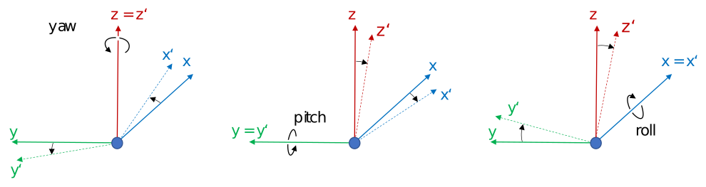
Figure 3 shows a right-handed coordinate system.
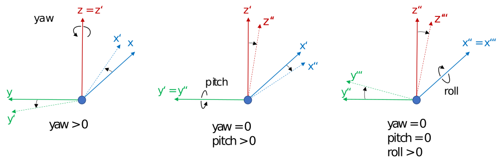
Figure 4 shows the positive axes and positive directions of the corresponding angles.
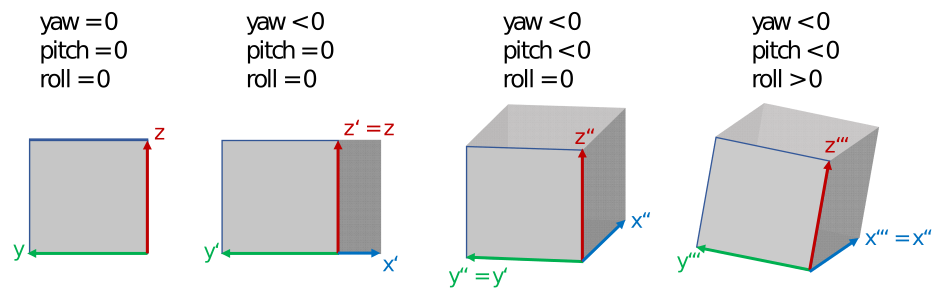
Figure 5 shows the different states of a coordinate system with defined rotations. x’/y’/(z’=z) denotes the coordinate system after rotating x/y/z with the heading angle around the z-axis. The coordinate system x’’/(y’’=y’)/z’’ denotes the coordinate system after rotating x’/y’/z’ with the pitch angle around the y’-axis. The final rotated coordinate system (x’’’=x’’)/y’’’/z’’’ is obtained after rotating system x’’/y’’/z’’ with roll angle.
Each 3D model has an individual reference frame. Individual nodes of an object may have local coordinate frames, for example, each wheel of a vehicle.
7.2.2.1 World coordinate system
A coordinate system of type (x, y, z) that is fixed in the inertial reference frame of the simulation environment has the xw- and yw-axes parallel to the ground plane and the zw-axis pointing upward.
Neither the origin nor the orientation of the world coordinate system is defined by ASAM OpenMATERIAL 3D. Nevertheless, the origin of the world coordinate system in an ASAM OpenMATERIAL 3D environment should coincide with the origin of a corresponding ASAM OpenDRIVE map (if available). The origin of the world coordinate system in ASAM OSI should also be aligned with these two coordinate systems.
7.2.2.2 Local coordinate system
Top-most local coordinate frames of 3D assets (so-called reference coordinate frames) in ASAM OpenMATERIAL 3D are defined in the center of the bounding box of the corresponding asset, projected to the bottom of the bounding box. By static transformations, these coordinate frames may be synchronized with reference coordinate frames in ASAM OpenSCENARIO XML and ASAM OSI. Table 16 provides an overview of the translations between ASAM OpenMATERIAL 3D asset reference coordinates and ASAM OpenSCENARIO XML and ASAM OSI reference coordinates.
| Standard | Coordinate System | Transformation |
|---|---|---|
ASAM OpenSCENARIO XML |
Vehicle |
The origin is the center of the rear axle projected to the ground. Add the x-coordinate of the rear axle from the vehicle asset metadata to the ASAM OpenMATERIAL 3D reference frame. |
ASAM OSI |
Moving or stationary object |
The origin is in the center of the bounding box. Add half of the height of the asset defined as the maximum z-coordinate in the bounding box to the ASAM OpenMATERIAL 3D reference frame. |
ASAM OSI |
Host vehicle |
The origin is the center of the rear axle. Add the x- and z-coordinate of the rear axle from the vehicle asset metadata to the ASAM OpenMATERIAL 3D reference frame. |
Besides reference coordinate frames, 3D assets may incorporate other local coordinate frames, see Section 7.3.1, "Object classes introduction".
7.2.3 Naming conventions
7.2.3.1 General
The following naming conventions apply to ASAM OpenMATERIAL 3D geometry files:
-
The 3D model file and the related 3D asset file shall have the same base name. Example:
Example.gltf,Example.xoma -
The naming convention inside the 3D model file (contains 3D information) shall follow the capital Snake_Case definition, to improve human readability and enable consistent parsing of the file structure.
-
The naming convention inside the 3D asset file (contains metadata) shall follow the lowerCamelCase definition, to allow a consistent naming convention in all JSON files and consistent parsing.
-
Keywords are predefined names for objects inside the node structure.
7.2.3.2 Node structure
Every node structure for a 3D object uses predefined keywords to allow a consistent naming convention and parsing. Some keywords are already defined by ASAM OpenMATERIAL 3D, and more may follow in future versions. Users may define additional keywords as needed. The following rules apply:
-
All components shall be named according to the capital Snake_Case definition, starting with uppercase letters.
-
Group nodes (also known as empty nodes or parent nodes) shall have "Grp_" as a prefix.
-
Iterators shall be added as suffixes. In the documentation, iterator names are written in angled brackets. Example:
<type_idx>. In the node name itself, the iterator names are replaced by integer values, starting from 0. -
Sequence of suffixes:
-
1: Iterator
-
2: Type Enumerator
-
3: Subtype Enumerator.
-
-
The predefined keywords shall be used for the corresponding asset parts and can be found in the corresponding subchapters.
7.2.3.3 Metadata
The following rules for metadata apply:
-
Fields shall be named according to the lowerCamelCase definition, starting with lowercase letters.
-
Naming of custom properties shall follow the predefined keys.
-
Objects, arrays (lists), and enums shall follow the notation in the corresponding JSON files.
7.2.4. 3D asset file
The 3D asset file provides metadata as well as a mapping table to ASAM OpenMATERIAL 3D material property files. This information extends the geometry of an asset given in standard 3D model file formats, for example, glTF, FBX, or USD. The 3D asset file is in JSON format with the file extension .xoma. The asset file shall have the same file name as the accompanying 3D model. The following is an example of a 3D model file in glTF format with an accompanying 3D asset file:
-
my-model.gltf -
my-model.xoma
7.2.5 Asset type
The assetType property of the 3D asset file distinguishes assets that represent an individual object ('object') from assets that represent a collection of objects ('scene').
The value 'scene' is deprecated as of ASAM OpenMATERIAL 3D 1.1.0. It is replaced by the concept of referencing external assets described in the following section. The value is retained for backward compatibility and should not be used in new assets.
7.2.6 References to external assets
Some 3D objects are not built from a single asset, but from variable compositions of several assets. Examples are vehicles with roof racks or bicycle carriers, and environments that are built up from separate layers or enhanced with additional objects. To accommodate these use cases, ASAM OpenMATERIAL 3D allows external assets to be referenced from the 3D asset file.
An external asset is referenced by associating its 3D asset file with a node of the overarching asset. This node acts as the parent of the external asset and determines its spatial placement and orientation. The references are given in the externalAssetReferences property of the 3D asset file, as a list of pairs of a parent node and a path to the 3D asset file of the external asset.
For example, a Grp_Wheel_Steering_Rotating_<axle_idx>_<wheel_idx> node in a vehicle asset can act as the parent node for interchangeable car wheels that are each referenced from an external asset.
7.2.7 Material replacement
Material names in a 3D data file are used as keys into the material mapping file, see Section 7.6, "Mapping schema". This requires the material names in the 3D data file to match the keys of a shared mapping table, which is not always possible when a 3D model is reused from another source.
The materialReplacements property of the 3D asset file resolves this without modifying the 3D data file. It maps a material name from the 3D data file to a replacement name or an RGB code. The replacement value, rather than the original material name, is then used as the key into the material mapping file.
7.2.8 Geometry properties
Some physical properties of an object cannot be derived from its surface geometry alone. For example, a wall or a window may be modeled as a single surface, although its physical thickness affects the propagation of sensor signals through it.
The geometryProperties property of the 3D asset file assigns such properties to individual nodes of the 3D data file.
Currently, only the thickness property is defined.
It specifies the extrusion along the surface normal, in meters, applied on the side opposite the viewer.
7.2.9 Requirements
-
The geometry of the object shall be in real-world scale, using meters as the unit of length.
-
The object’s origins and pivot points shall coincide with position and orientation of the origin of the object’s reference coordinate frame, unless otherwise specified.
-
Meshes shall not contain problematic primitives, such as doubled, isolated, coincident, coplanar, or degenerate primitives.
-
Meshes shall have outside facing normals. Soft or hard edges shall be set correctly.
-
Meshes shall not be empty and shall not contain multiple levels of detail (LoDs).
-
Meshes shall be triangulated. Potential normal maps shall match that triangulation.
-
Rendering materials shall support physically based rendering (PBR) workflows and there shall not be any geometry without an assigned material.
-
Additional requirements apply when ASAM OpenMATERIAL 3D assignment textures are used:
-
UV channel 1 shall be used for assignment textures.
-
UV islands shall have margins between them, so that assignment texture interpolation errors are avoided.
-
There shall not be any geometry without UV coverage.
-
7.2.10 Recommendations
-
UVs should not overlap and should lie within the 0-1 UV space.
-
Elongated primitives should be avoided, because they fit poorly into acceleration structures.
-
Alpha-textured meshes should be optimized to minimize the amount of alpha testing required.
-
Meshes should not have holes or gaps.
-
Meshes should have a clean edge flow.
-
N-gons should not be used.
-
Faces should be one-sided.
-
An object’s shape should have the lowest possible number of polygons.
-
Texel density should be homogeneous and as low as possible.
-
UV stretching should be minimized.
-
Naming of files, nodes, meshes, and materials should be meaningful.
-
The use of multiple PBR maps is encouraged, for example, albedo, roughness, metallic, and normal maps.
-
Smaller objects should have one material per object, for example, baked traffic cone. Larger objects should contain multiple seamless repeatable materials, for example, brick building.
7.2.11 Lighting
The lighting concept of ASAM OpenMATERIAL 3D distinguishes between discrete light sources, for example, point lights or spotlights, and emissive materials. This allows both physically simulated light sources and visually emissive elements to be defined in a standardized way.
7.2.11.1 Discrete light sources
Discrete light sources are active light sources that emit light into the environment, for example, point lights or spotlights. They are defined in the 3D asset file using the lightDefinitions property.
Each discrete light source is associated with a corresponding node in the 3D data file. This node determines the spatial placement and orientation of the light within the asset.
If the associated node follows the predefined naming convention for lighting group nodes of a specific object class, the lighting function is defined implicitly. For example, a node named Grp_Light_Low_Beam_Left_0 in a vehicle asset indicates that the light represents the left low beam. In a simulation, this light is activated when the corresponding vehicle function, the low beam, is enabled.
If a generic node name is used, no standardized function can be derived. In such cases, the simulator may assign a lighting function arbitrarily, which results in non-standardized behavior.
Additional properties of discrete light sources, such as intensity, color, and beam shape, can be configured in the 3D asset file as defined in the corresponding JSON schema.
7.2.11.2 Emissive materials
Emissive materials are defined in the 3D data file and mapped in the 3D asset file using the emissiveLightMapping property.
As with discrete light sources, emissive materials are associated with nodes in the 3D data file. In this case, however, the node does not define any spatial placement. It is used solely to derive the lighting function from its name. For example, a material associated with the node Grp_Light_Indicator_Left_0 corresponds to the left turn indicator. In a simulation, the emissive effect of the indicator is activated by modifying parameters of the corresponding material or by activating its textures.
As with discrete light sources, generic node names result in non-standardized behavior, and the simulator decides the mapping.
The visual appearance of emissive materials is defined by the materials in the 3D data file. These materials are referenced in the 3D asset file.
In addition, emissive textures can be specified in the 3D asset file. A masking texture may be used to selectively control emissive regions for specific lighting functions.